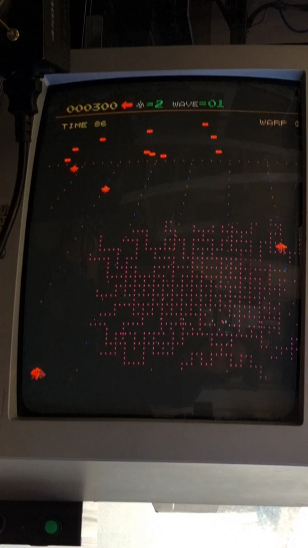
Juno First - Garbled Graphics, 1983 Arcade Board Repair
KONAMI Juno First(1983)
It came with worse condition than the customer’s video. The sprites are all solid colour squares, with unstable “scanlines” indicating VRAM issues.
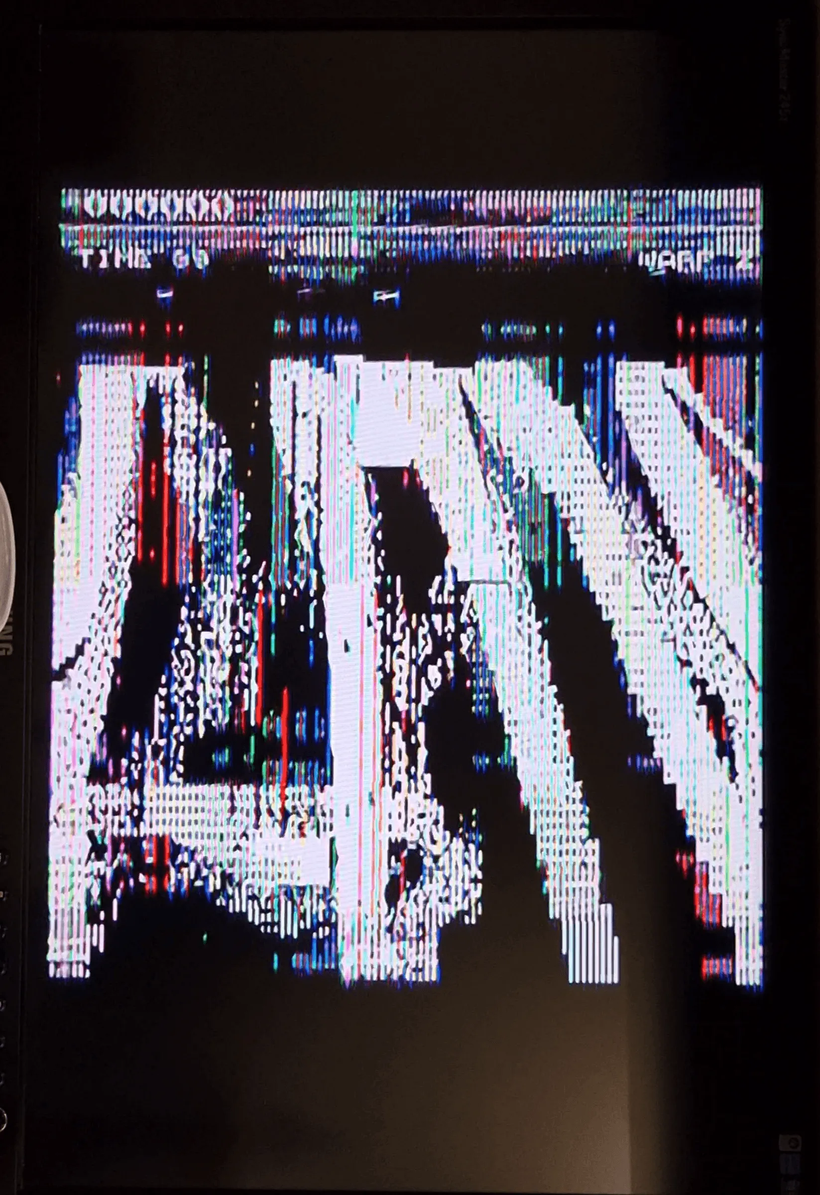
Upon test, it has no sound, doesn’t register shoot button or down direction(sometimes down is stuck instead of no response) at least.
The gameplay logic seems okay, with demo gameplay showing shooting bullets and high score board too.
The main issue might be located in video output part, along with audio missing and input issue.
Diagnosis
First check all the ROMs. 1-9 are 2764, 11-13 are 2764, 14-15 are 2732. Compared with Internet dumps, only 14 and 15 are good. All CPU ROMs and blitroms are bad, total 12x 2764 EPROMs.
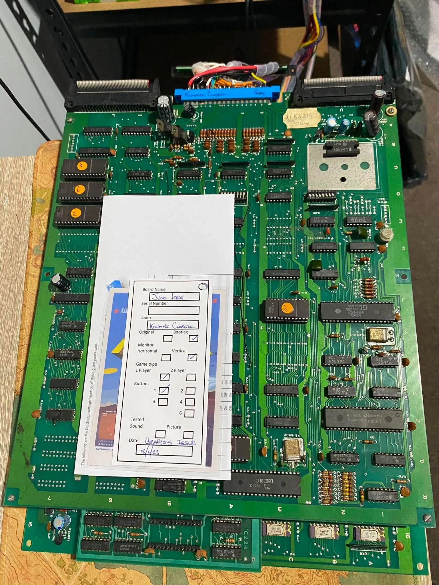
The repair
ROM issues:
Managed to reprogrammed all the ROMs using existing chips. Still runs but with corrupted latching graphics.
Graphics issues:
After running it for a few more times, it went into a state that as soon as the shooting screen appears the whole game is halted.
Blit ROMs seem never enabled. Few bus activities on the sound part.
Traced blit ROMs /OE pin back to 6D (LS273) and 5L (LS273) both confirmed bad. Along the way there’s a same Mitsubishi brand LS273 6F, will replace altogether given the high failure rate.
There are several other Mitsubishi LS273 on the top board, at least one on the bottom board. Source more LS273s.
Replaced 3 LS273s, graphics slightly better as you can sometimes see the player propeller’s fume/fire.
Tested 6E LS244 transceiver is bad. Piggybacked a new LS244 shown explosion effects, etc. And blit ROM 7C and 7D gets /OE signals, but 7E hasn’t yet. Anyway 6E needs to be replaced.
6E replaced. Back to the screen where the client sent me the video - no latching pixels, player’s propeller visible, explosion visible, “Juno First” title are blocks.
While doing more tests, horizontal lines start to appear and gradually cover the whole screen.
This gonna be a tough one.
Now suspect either the ROM chips aren’t outputting data with high enough clean voltage. This can be seen on blit ROMs’ all RD0-RD7 bits. Or it could be a faulty 7J 74LS273 load the voltage down.
Tried to lift the 7J’s input pin 14 (RD0) and pin 13(RD2). No obvious voltage increase on the RD data bus, however due to the two pins are floaty, the corresponding output gives a HIGH voltage so the screen starts to show enemies’ sprite with a block and player’s sprite with a block too.
Although I think 7J LS273 maybe still good as it latches a floaty input to HIGH output with expected behaviour, let’s try replace it with a new one see if it improves. I believe the missing graphics has a lot to do with zero output from 7J.
Replaced 7J LS273, still no improvements.
Turns out the blit ROM isn’t getting half of its address right. There’s another 74LS244 is bad at 7A (another one at 5A probably better replaced altogether).
Piggybacked 7A shows a lot better graphics. Definitely needs replacement. Till this point, I don’t think the graphics issue are caused by VRAM anymore.
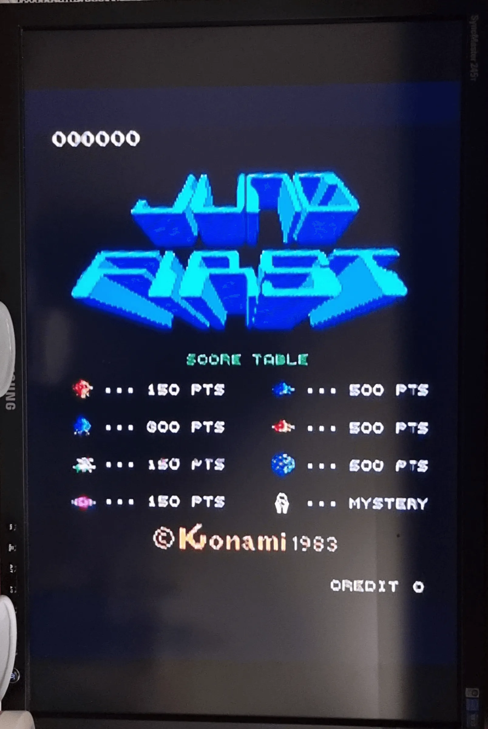
Replaced 7A and 5A, graphics seems normal now, albeit the horizontal line appears after warming up.
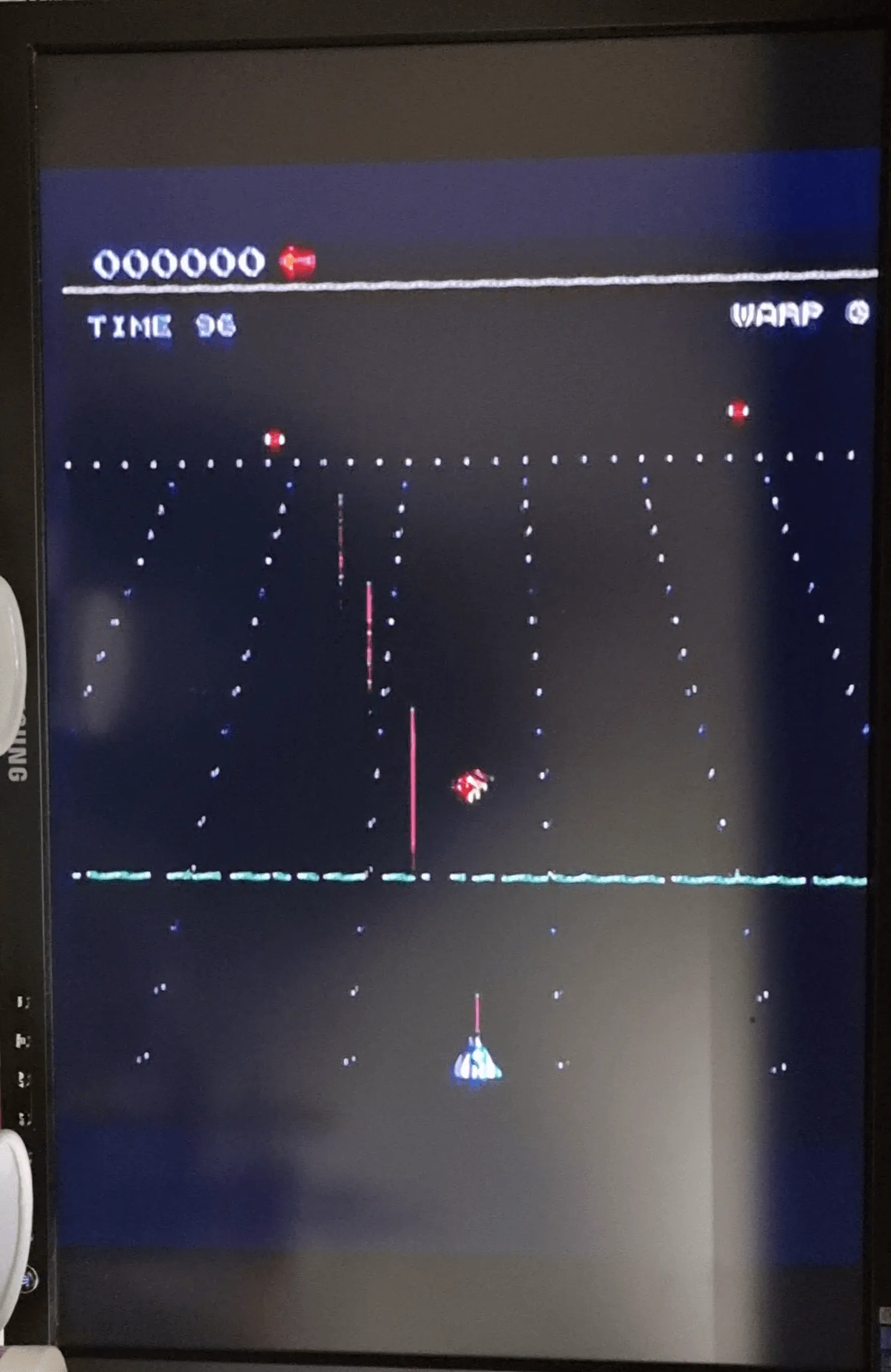
The sticking horizontal lines seems to be VRAM thermal related issue. They needs +12V +5V and -5V three voltages to operate. Upon testing when lots of horizontal lines, almost interleaved the whole screen, the +12V and -5V power rail swung a lot. Give them a blower to cool down seems fixed the pixels and the power rails swung back down.
Since I was testing it with cardboard inserted between the top and bottom PCBs, it could have made the thermal condition worse.
Confirmed it’s thermal related. A ventilation fan turns on after the horizontal lines cover the screen, and it gradually disappears. Notify the customer about this behaviour. 16 VRAMs are too costly to replace.
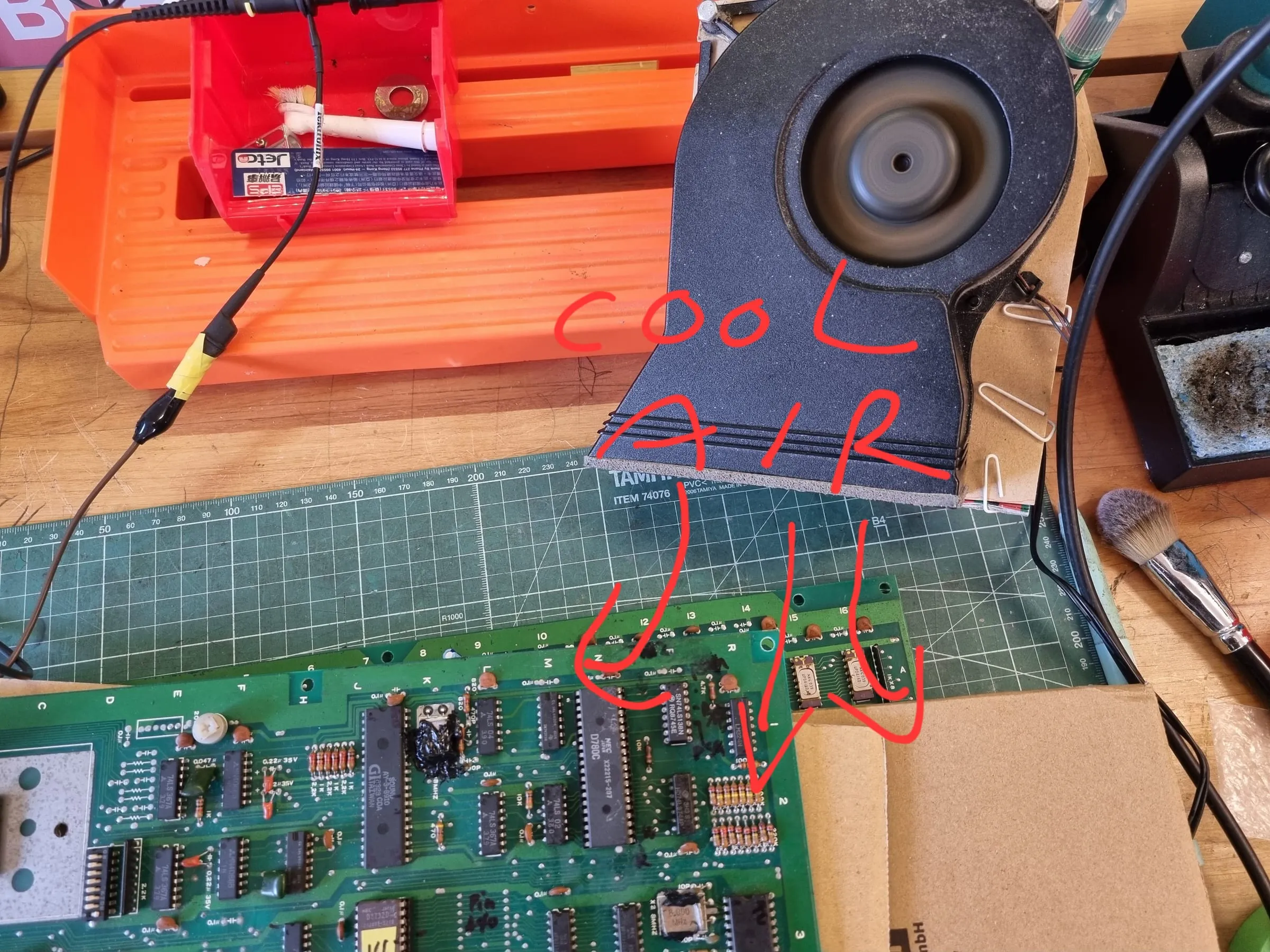
Added 15x 100nF ceramic capacitors hoping to improve the VRAM stability, no obvious effect on the single middle horizontal line, but -5V and +12V power rail waveform are much flatter, huge improvement.
The purple -5V wire on the Konami connector went broken during tests. Resoldered it back and it’s harder to reproduce the sticking horizontal line. Maybe it’s the dodgy -5V connection after all?
Audio issues:
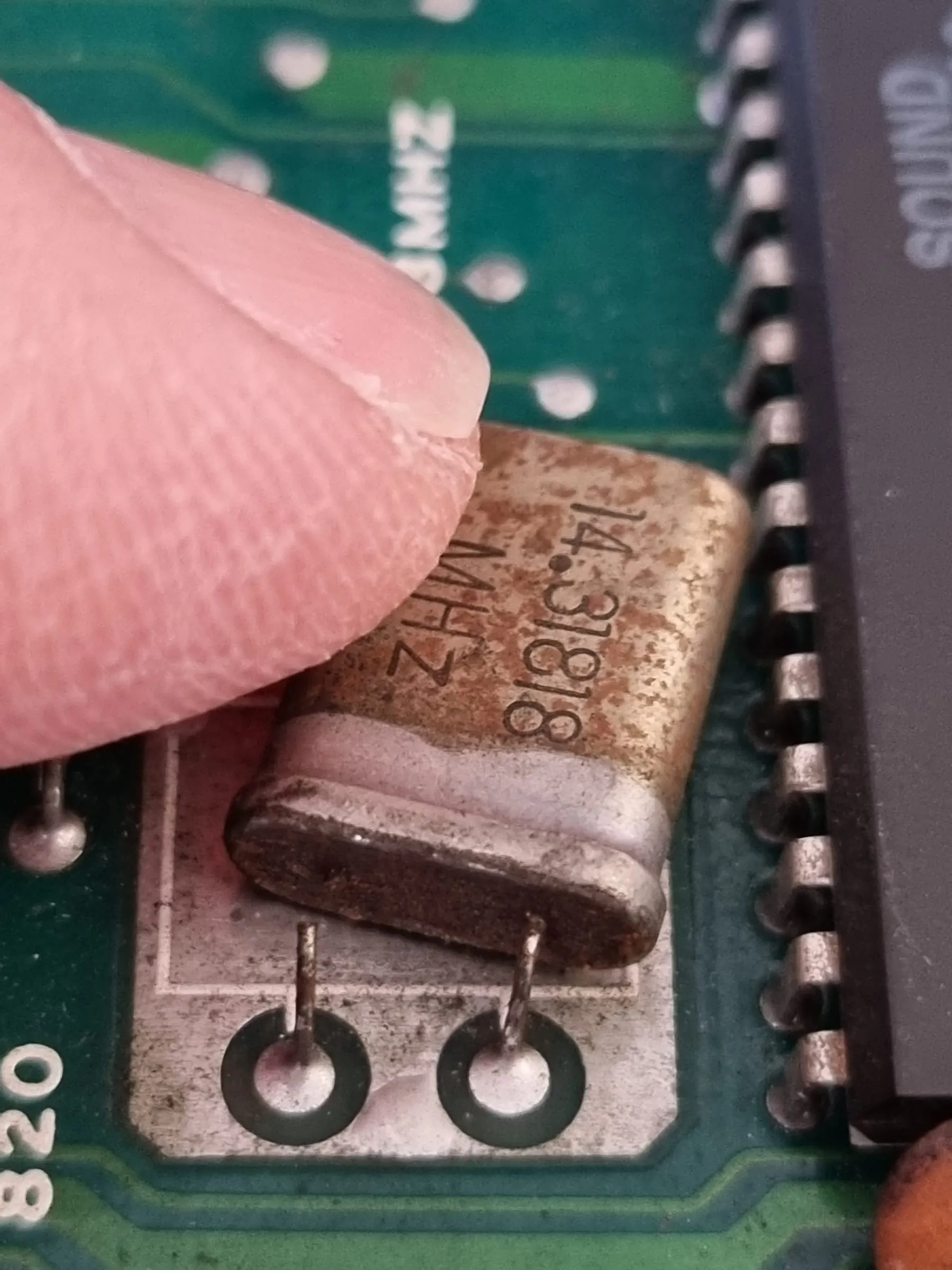
There’s a broken leg on the AY8910 crystal’s leg(14.31818MHz). Tried to fix the broken leg and got weak frequency signals, but still managed to get something out from 1L (74LS04). The AY8910 chips seems getting good frequency but output no data. CA0 - CA2 are all LOW while CB0 - CB5 are all HIGH. Still no sound.
DM0-DM7 bus is sometimes okay with relative low voltage pulse but still should register signals, sometimes totally unusable seems only driven by some chip then released. This should make AY8910 not generating analog sound. DM bus connected to 3J(2732 ROM) and sound CPU Z80, and 3H (LS374). I would suspect the ROM or the /OE pin of the ROM.
Also found 1P (LS138) decoder generating important chip select signals for AY8910, for 2732 ROM, and for Sound RAMs (3M, 3N, both 2114 RAMs). Piggybacked 1P with new LS138 found not very useful.
Piggyback Z80 with a known good one. The AM12, AM13, AM14 signals became weaker but sometimes it generating an initial complete sound clip upon boot. Sometimes putting the probe on Z80 pin 2,3,4 would help trigger this sound too. The sound isn’t noise but the choice of sound clip seems random. Z80 could have been faulty too
Hypothesis: the problem is DM bus is usually left floaty, no one is driving DM bus. No ROM, no RAM. The driving signals all came from 1P (LS138) Z80 is faulty - some evidences back it ROM J3 is faulty - although checked the dump, the low voltage output backs it 1P LS138 is faulty - piggyback doesn’t help a lot Sound RAM is faulty - could affect DM bus Other chips on DSS bus are faulty, like 3D, 2E (LS367) and 3H (LS374)
Reprogrammed ROM 14(audio CPU ROM).
1L 74LS04 may be bad, no usable chip now so not verified. The 14.318MHz crystal again have very degraded performance, no clean frequency is output.
Z80 is quite likely be bad.
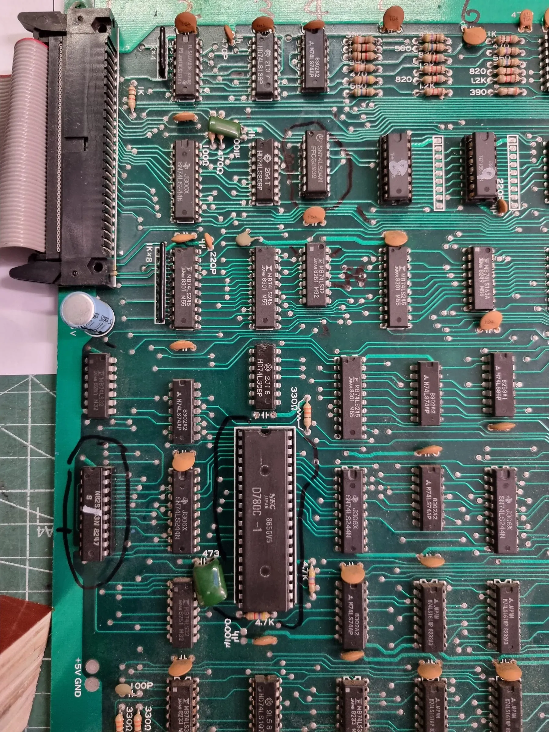
Replaced 1P LS138. Replaced Z80. Sound appears, seems proper sounds. 14.318MHz crystal seems back to normal, but later it proves it’s only temporarily.
Silicon glue applied to two fragile crystals to seat them properly.
20260801 UPDATE: after two weeks and checking again, the 14.318MHz crystal is bad again, causing no sound. It isn’t worth fixing the leg, it needs to be replaced.
Found a donor board happened to have a same 14.318MHz crystal, measured 14.218MHz, should be good to be a replacement
Replaced crystal and replaced Z80 with another donor Z80, sound is back now.
Control issues:
The Konami connector doesn’t have 1P’s shoot2 button wired, no 2P coin button wired. Incomplete to test. Added a SHOOT2 button wire to the Konami connector, and the game is playable now.
Final result
Stress tested. No issue found. The board is fully repaired.